
Demagnetization Is Not a Sudden Failure
The common mental model of magnet demagnetization is a step function: the motor works normally, then the magnets fail, and the motor stops producing torque. That is not how it happens in practice. Demagnetization in NdFeB motors is almost always partial and gradual - the magnets lose a fraction of their remanence, the motor produces slightly less torque at the same current, and the control system compensates by increasing current, which produces more heat, which accelerates further demagnetization. The failure mode is a slow drift, not a cliff.
By the time partial demagnetization is detectable as reduced motor performance, the magnets have typically lost 5–15% of their original Br. At that point, the demagnetization is irreversible. The magnets cannot be re-magnetized in the motor without complete disassembly and return to the magnetizing fixture. For a deployed robot joint or a sealed servo actuator, that means a full rebuild.
This article covers the three mechanisms that cause demagnetization in operating motors, how to calculate the demagnetization risk for a given magnet grade and operating point, and what to specify to ensure the design has adequate margin.
1. The Three Demagnetization Mechanisms
Thermal demagnetization, short-circuit demagnetization, and operating-point demagnetization are distinct mechanisms with different causes and different solutions. Confusing them leads to wrong fixes.
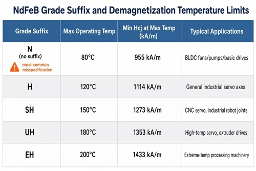
Thermal demagnetization occurs when the magnet temperature exceeds the point where the coercivity Hcj drops below the level required to resist the motor's own demagnetizing field. This is a threshold effect: below the critical temperature the magnet is stable, above it demagnetization begins and is irreversible on cooling. For N-grade NdFeB (no thermal suffix), the Hcj drops steeply above 80°C. The critical temperature for a given motor design depends on the air gap field and the magnet volume - a motor with a thin magnet section and a large demagnetizing field may demagnetize at 90°C where a better-designed motor with the same grade would be stable to 120°C.
Short-circuit demagnetization occurs during fault conditions - phase-to-phase shorts, drive faults, or regenerative braking events - where the stator current produces a demagnetizing field that exceeds the magnet's Hcj at operating temperature. In a normal operating condition, the peak current in a properly designed motor is not high enough to demagnetize even N-grade magnets. During fault conditions, current can reach 5–10× rated value for milliseconds. Whether that pulse demagnetizes the magnets depends on the magnet thickness, Hcj at temperature, and the duration of the fault.
Operating-point demagnetization is the most insidious because it can occur at normal operating temperatures with no fault events. It happens when the motor is designed with insufficient magnet thickness for the required peak torque, so that at peak current the demagnetizing field approaches or exceeds Hcj. Each torque pulse leaves the magnets slightly weaker. Over time, performance drifts down. This is commonly misdiagnosed as bearing wear or winding degradation.
2. The Demagnetization Load Line
The key tool for demagnetization analysis is the magnet operating point on the B-H demagnetization curve. Every NdFeB magnet has a published B-H curve at multiple temperatures - typically 20°C, 100°C, 150°C, and sometimes 180°C. The motor designer calculates the operating point: the combination of B (flux density in the magnet) and H (demagnetizing field applied to the magnet) at the worst-case operating condition, which is typically peak current at maximum operating temperature.
The operating point must stay to the right of the "knee" in the B-H curve - the point where the curve begins to curve sharply downward. Below the knee, any further increase in demagnetizing field causes irreversible flux loss. Above the knee, the demagnetization is reversible: the flux temporarily reduces under the applied field but recovers when the field is removed.
For N42SH magnets at 150°C (a common grade for industrial servo applications), the knee of the B-H curve occurs at approximately H = -950 kA/m. If the motor design results in a peak demagnetizing field of -700 kA/m at 150°C and peak current, there is a 250 kA/m margin above the knee. That margin should be at least 150–200 kA/m for a conservative design, accounting for magnet-to-magnet variation in Hcj (typically ±50 kA/m in production) and for temperature measurement uncertainty.
3. Grade Suffix Selection: What the Letter Actually Means
The thermal suffix in NdFeB grade designations - H, SH, UH, EH - indicates the maximum operating temperature at which the coercivity Hcj meets the minimum spec. N42 without a suffix is rated to 80°C maximum operating temperature. N42H is rated to 120°C. N42SH is rated to 150°C. N42UH is rated to 180°C. N42EH is rated to 200°C.
These are not absolute temperature limits where the magnet instantly fails - they are the temperatures at which the minimum Hcj spec is met. Above the rated temperature, the magnet may still be stable depending on the specific demagnetizing field in the motor. Below the rated temperature, there is additional Hcj margin.
The grade selection error that causes the most field failures: specifying the suffix based on the winding temperature rather than the magnet temperature. In an enclosed servo motor with forced convection cooling on the housing, the winding can reach 130°C while the magnet surface temperature (which directly affects Hcj) reaches 110°C because the magnet is closer to the cooled housing wall. Conversely, in a frameless motor where the rotor is surrounded by vacuum or low-conductivity structure, the magnet temperature can exceed the winding temperature during sustained operation. The magnet temperature must be measured or modeled - it cannot be inferred from the winding temperature without a thermal model of the motor geometry.
4. Practical Margin Requirements by Application
Industrial servo axes (CNC, industrial robots): design for 30% Hcj margin above the knee at maximum winding temperature. The 30% accounts for ±5% production variation in Hcj, temperature measurement uncertainty, and the fact that fault conditions will occasionally expose the motor to above-rated currents.
Collaborative robot joints and direct-drive torque motors: design for 40% margin. Collaborative robots are frequently used near their torque limits in contact-rich tasks, and peak current during unexpected contact events can briefly exceed rated current. The cost of a field rebuild is high enough that conservatism pays off.
UAV propulsion motors: design for 25% margin at the rated continuous temperature. UAV motors are rarely at peak current for sustained periods - peak current occurs only during takeoff and aggressive maneuvers. At cruise, the demagnetizing field is well below peak. The 25% margin covers the takeoff condition.
High-temperature applications (extruder drives, processing machinery near heated tooling): use SH or UH grade and design for 35% margin at the maximum expected magnet temperature, not the ambient temperature. If the motor is bolted to a 180°C heated platen, the magnet temperature will approach 180°C in steady state regardless of the winding temperature.
5. What to Request from Your Magnet Supplier
A complete demagnetization resistance specification includes three items that every competent magnet supplier should be able to provide:
First, the full B-H demagnetization curve at the operating temperature, not just the room temperature curve. For a motor rated to 150°C magnet temperature, you need the 150°C curve. Many datasheets only show 20°C data - this is insufficient for demagnetization analysis.
Second, the minimum Hcj at temperature across the production lot, not the typical or nominal value. Production NdFeB has Hcj variation of ±3–5% at the same grade. A motor designed to the nominal Hcj will have units in production that demagnetize at operating conditions the design analysis said were safe.
Third, a flux density mapping measurement on a sample batch of magnetized magnets. The measurement confirms that the magnetization level achieved in production matches the specification. It also provides the baseline for incoming inspection - future production lots can be compared against the baseline to detect magnetization process drift before it affects motor performance in the field.
HIMAGNET provides B-H curve data at operating temperature, minimum Hcj specs by production lot, and flux density mapping services for motor magnet qualification. For demagnetization margin analysis support, contact our engineering team with your grade, operating temperature, and peak demagnetizing field.