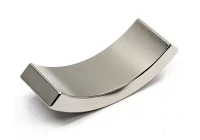
The Problem That Shows Up at Low Speed
Cogging torque is the periodic torque ripple that occurs in permanent magnet motors even when no current is flowing. It comes from the interaction between the rotor magnets and the stator teeth - the magnet flux wants to align with the lowest reluctance path, which means it wants to align with a stator tooth rather than a slot. As the rotor turns, the flux alternately aligns and misaligns with successive teeth, producing a torque waveform with peaks and valleys at a frequency determined by the pole and slot count.
For most applications, cogging torque is a minor nuisance. For precision servo systems, direct-drive motors, and robot joints that need smooth motion at low speeds, it's a primary design constraint. A collaborative robot arm moving at 5 RPM through a precision assembly operation will make every cogging torque peak visible as a velocity ripple in the position error - and that velocity ripple appears as dimensional error in whatever the robot is assembling.
This article covers what causes cogging torque, how to measure it, and which magnet design approaches actually reduce it versus which ones just move the problem around.
1. What Sets the Cogging Frequency and Amplitude
Cogging torque frequency is determined by the least common multiple (LCM) of the pole count and slot count. A 10-pole, 12-slot motor has LCM(10, 12) = 60, so there are 60 cogging torque peaks per revolution. A 10-pole, 15-slot motor has LCM(10, 15) = 30, so there are only 30 peaks per revolution. Higher LCM means more peaks per revolution at lower amplitude each - the total energy in the cogging waveform is roughly constant, but it gets distributed into more, smaller peaks.
This is why fractional-slot winding configurations - where the slot-per-pole-per-phase ratio is not an integer - are popular in direct-drive and low-speed servo applications. A 10-pole, 12-slot configuration (0.4 slots per pole per phase) has higher LCM than a 10-pole, 9-slot configuration (0.3 slots per pole per phase), which means lower cogging amplitude per cycle at the cost of higher frequency.
Cogging amplitude is determined by the magnet flux density, the magnet arc-to-pole-pitch ratio, the air gap length, and the stator slot geometry. Of these, the magnet arc ratio is the one the magnet supplier can control. The others are fixed by the motor lamination design.
2. The Magnet Arc Ratio: The Only Magnet Parameter That Directly Affects Cogging
For a surface-mounted magnet motor, there is an optimal magnet arc ratio - the ratio of magnet arc length to pole pitch - that minimizes cogging torque. This optimum exists because the cogging torque is related to the derivative of the total air gap magnetic energy with respect to rotor position, and the derivative passes through zero at specific arc ratios.
For a 10-pole, 12-slot motor with a typical stator slot opening of 2–3mm in an 80mm stator bore, the cogging-minimizing magnet arc ratio is approximately 0.833 (five-sixths of the pole pitch). Using a 0.75 arc ratio - one full pole pitch minus one slot pitch - also produces near-zero cogging for this combination. The exact optimum depends on the slot opening width and air gap length; a simulation with the actual lamination geometry is required for precise optimization.
What the arc ratio cannot fix: if the lamination slot opening is wide relative to the magnet pitch, cogging will be high regardless of arc ratio. Wide slot openings cause large reluctance variation as the rotor turns. The magnet sees a "bump" every time a slot passes by. No arc ratio optimization eliminates this if the slot opening is more than about 20% of the slot pitch.

3. Skewing: Effective but Costly
Axial skewing - rotating the magnet or the stator laminations by one slot pitch along the axial direction - is the most reliable method for reducing cogging torque. When the magnet is skewed by one slot pitch, the cogging peaks at each axial position are phase-shifted relative to each other, and the peaks cancel when summed axially. In theory, perfect skewing by exactly one slot pitch reduces cogging to zero. In practice, manufacturing variation in the skew angle leaves residual cogging at 10–20% of the unskewed value.
The cost of skewing is real. Skewed magnets are more expensive to manufacture - the angled geometry requires custom fixtures and increases material waste. Axially skewed laminations require a rotated lamination stack that is harder to assemble and increases motor length slightly. The most common compromise is step-skewing: using two or three axial magnet segments per pole, each shifted by a fraction of the slot pitch. Two-segment step-skewing achieves about 70% cogging reduction compared to unskewed; three-segment achieves 85–90%.
For a 60mm axial-length motor, two-segment step-skewing means each magnet segment is 30mm long with a 1/2 slot pitch angular offset between them. At 12 slots and 80mm bore diameter, one slot pitch is 20.9mm arc length, or about 9.4° at the rotor surface. The angular offset between segments is therefore 4.7°. This is achievable with standard magnetizing fixtures and does not require unusual magnet geometry.
4. Magnet Edge Chamfering and Pole Arc Shaping
Chamfering the magnet edges - reducing the radial thickness near the magnet ends - produces a sinusoidal radial flux density distribution rather than a trapezoidal one. This reduces the harmonic content of both the back-EMF and the cogging torque simultaneously.
The quantitative effect depends on the chamfer depth relative to the magnet thickness. A chamfer depth equal to 20% of the magnet radial thickness reduces cogging amplitude by 35–50% compared to a flat-faced magnet, while reducing back-EMF fundamental by only 3–5%. The tradeoff is favorable when the design goal is low cogging and acceptable back-EMF waveform quality.
Pole arc shaping - varying the air gap along the magnet arc by using a magnet with a curved outer surface that is not concentric with the rotor - is more effective but requires more precise machining. The curved surface creates a sinusoidal variation in air gap length that produces a near-sinusoidal flux density distribution. Combined with an optimal arc ratio, this can reduce cogging to below 0.5% of rated torque without skewing.
5. Cogging Torque Specification and Measurement
Cogging torque is specified as a percentage of rated torque. For general industrial servo applications, 2–3% is acceptable. For collaborative robots and direct-drive systems, 1% is the typical target. For medical imaging, semiconductor handling, and precision optical positioning, 0.3–0.5% is required.
Measurement is done by slowly rotating the motor shaft (typically at 1–5 RPM with no current applied) while measuring shaft torque with a precision torque sensor. The peak-to-peak cogging torque over one electrical cycle is the reported value. The measurement must be done at a speed slow enough that inertial effects are negligible - at 5 RPM, for a motor with 50g·cm² rotor inertia, the inertia torque at 1 Hz electrical frequency is less than 0.01 N·m, which is negligible compared to a 0.1 N·m rated torque motor.
When specifying cogging torque requirements to a magnet supplier, provide: pole count, slot count, magnet arc ratio, air gap length, and target cogging as a percentage of rated torque. The supplier can confirm whether the magnet geometry is compatible with your target, or recommend arc ratio adjustments and skew configurations that will achieve it.
6. What Cannot Be Fixed with Magnets Alone
Cogging torque from wide stator slot openings cannot be fixed by magnet design. The only solutions are: closing the slot openings with magnetic slot wedges (adds cost and assembly complexity), using a lamination design with narrower slot openings (requires redesigning the lamination), or accepting the cogging level and using current injection (active cogging compensation in the drive) to cancel it in closed-loop operation.
Active cogging compensation works by injecting a feedforward torque command that is the inverse of the measured cogging torque profile, synchronized to the encoder position. This is effective and widely used in high-performance servo drives. It does not eliminate cogging from the motor physics - it compensates for it electrically. The compensation accuracy depends on how well the measured cogging profile matches the actual motor, and any variation across production motors requires individual calibration.
For low-volume high-precision applications, individual calibration is feasible. For volume production, it adds cost and complexity. The better long-term solution is to get the cogging low enough through lamination and magnet design that active compensation is optional rather than required.
HIMAGNET supplies arc segment magnets with optimized arc ratios, step-skewed configurations, and chamfered edge profiles for cogging torque reduction. For cogging analysis support on your motor design, contact our engineering team with your pole count, slot count, and cogging target.