The Industrial Servo Problem Is Consistency, Not Peak Performance
UAV motors are specified for peak thrust. Humanoid robot joints are specified for peak torque. Industrial servo motors are specified for something more demanding than either: consistent, predictable torque output over ten million cycles, at rated temperature, with the same performance on cycle one as on cycle ten million.
That requirement changes the magnet selection logic entirely. A UAV motor that loses 2% of its flux density after a season of racing is a minor inconvenience. An industrial servo on a precision assembly line that loses 2% of its torque constant over six months of production shifts causes rejected parts, recalibration downtime, and warranty claims. The economic consequences of gradual demagnetization in industrial servo applications are not proportional to the flux loss - they're proportional to the production value of the process the motor controls.
This is what makes industrial servo motor magnet selection different, and why picking a grade from a UAV or consumer motor reference is the wrong starting point.
1. Why Duty Cycle Thermal Dynamics Are the Core Design Variable
Industrial servo motors in CNC machining, robotic welding, and pick-and-place automation run at duty cycles that concentrate heat in specific patterns. A servo on a machine tool spindle might run continuous at 70% of rated torque for 6-hour shifts. A servo on a pick-and-place arm runs at peak torque for 80ms, then drops to near zero for 120ms, repeating at 5 Hz for 16 hours a day.
The steady-state winding temperature in the spindle application is predictable from rated current and thermal resistance. In the pick-and-place application, the winding temperature cycles, and the thermal time constant of the magnet assembly - typically 45–90 seconds for a 60–100mm frame servo - means the magnet temperature doesn't track the instantaneous winding temperature. It tracks a moving average with a lag. On a fast duty cycle with high peak currents, the magnet can reach temperatures 25–40°C above what a steady-state thermal model at average current would predict.
Specifying the magnet grade from average current is wrong. Specify from peak current duty at the thermal time constant of the magnet assembly. For most industrial servo applications in the 1–10 kW range, this means the effective magnet design temperature is 100–140°C, not the 80°C winding limit that appears on the motor datasheet.
2. IEC Thermal Class and What It Actually Means for Magnets
Industrial servo motors are rated to IEC thermal classes - Class F (155°C winding limit), Class H (180°C), Class C (above 200°C). These ratings apply to winding insulation, not to the magnets. The magnet temperature in a well-designed motor with internal cooling runs 30–60°C below the winding temperature at rated load, but in a motor operating above rated duty or with degraded cooling, the gap narrows.
The practical mapping between motor thermal class and magnet grade suffix:
| Motor Thermal Class | Typical Max Magnet Temp | Minimum Grade Suffix | Notes |
|---|---|---|---|
| Class F, forced cooling | 80–100°C | H | H suffix provides margin; N suffix marginal unless operating point is conservative |
| Class F, self-cooling | 100–120°C | H to SH | SH preferred for continuous duty applications; H acceptable with verified thermal model |
| Class H, forced cooling | 100–130°C | SH | SH baseline; EH for motors near rated current at 130°C magnet temp |
| Class H, self-cooling | 120–150°C | EH | EH or AH; verify BH curve at operating temperature - manufacturer datasheet often not sufficient |
| Class C / specialty | 150–200°C | SmCo or AH NdFeB | Above 150°C sustained, SmCo is the correct answer; NdFeB AH grades exist but SmCo is more stable |
3. The Demagnetization Accumulation Problem in Long-Cycle Applications
In a servo motor running 5,000 hours per year on a production line, the magnet experiences roughly 90 million electrical cycles at a 14-pole-pair configuration and 1,500 RPM rated speed. Each cycle where the operating point dips below the BH knee - even briefly, even by a small margin - contributes a small irreversible flux loss.
The problem is not the individual event. It's the accumulation. A magnet that loses 0.05% Br per 1,000 operating hours has lost 0.25% after one year. That sounds negligible. In a high-precision servo on a semiconductor bonding machine, 0.25% torque constant drift requires recalibration of the force control loop. Recalibration on a bonding machine takes the tool offline for 2–4 hours. On a 24/7 facility, this happens twice a year per machine. The cost of that downtime vastly exceeds the cost of specifying the next-higher coercivity grade at the design stage.
The correct specification approach: calculate the minimum Hcj required to keep the operating point 20% above the BH knee at maximum expected magnet temperature and maximum demagnetizing current. Then add one grade suffix above that minimum. The incremental cost is small. The incremental reliability is measurable.
4. Grade Selection by Industrial Servo Application
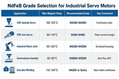
| Application | Duty Cycle | Max Magnet Temp | Recommended Grade | Rationale |
|---|---|---|---|---|
| CNC machining center (spindle servo) | Continuous 60–80% | 100–120°C | N42SH–N45SH | Long continuous runs; SH essential; lower BHmax grade acceptable if torque density permits |
| CNC axis servo (feed drive) | Cyclic, 30–60% | 80–110°C | N45H–N48H | Intermittent; H sufficient with proper peak current margin analysis |
| Industrial robot joint (6-axis arm) | Cyclic, 40–70% | 90–120°C | N42SH–N45SH | Similar to CNC spindle; enclosed joint housing limits convection |
| Pick-and-place / SCARA | High-frequency cyclic | 80–110°C | N45H–N48H | Peak currents high but short; verify demagnetization margin at peak current |
| Semiconductor / electronics assembly | Precision cyclic | 60–90°C | N48SH–N50SH | Low temperature but precision requires zero flux drift; SH provides long-term stability margin |
| Extruder / winding machine | Continuous near rated | 110–140°C | N42EH–N45EH or SmCo | Near rated current for hours; EH or SmCo depending on exact temperature |
5. What Separate Suppliers Cost You in a Servo Redesign
Industrial servo motor design cycles are long - 12–24 months from initial specification to qualified production. The magnet geometry is locked in at the first prototype build. If the magnets and the rotor laminations come from different suppliers, any geometry change - and there will be geometry changes during development - requires re-engagement with two vendors, two lead times, and two sets of first-article inspection paperwork.
In practice, most servo development teams go through 3–5 magnet geometry iterations between first prototype and production release. Each iteration that requires separate tooling at a separate magnet supplier adds 4–8 weeks to the schedule and eliminates the possibility of co-optimizing the magnet arc and lamination slot geometry together. The air gap tolerance budget, which directly determines torque ripple and cogging, is much easier to hold when both components are designed and manufactured with each other's tolerances in mind from the start.
6. Specification Checklist for Industrial Servo Magnets
- ☐ Calculate peak demagnetizing field at maximum transient current, not rated current
- ☐ Determine effective magnet temperature using thermal time constant model, not steady-state average current model
- ☐ Select grade suffix with 20% Hcj margin above BH knee at maximum magnet temperature
- ☐ Add one suffix above calculated minimum for long-cycle applications (>5,000 hours/year)
- ☐ Request B-H curves from production material at 20°C, 100°C, and 150°C - not datasheet typical values
- ☐ Specify flux density uniformity requirement: ±1.5% for precision servo; ±2.5% for standard industrial
- ☐ For applications above 130°C sustained: evaluate SmCo before committing to NdFeB EH/AH grades
- ☐ Confirm magnet supplier can provide matched arc segment geometry to your rotor lamination drawing
HIMAGNET supplies arc segment magnets for industrial servo motors with matched lamination coordination, production B-H data at operating temperatures, and engineering support through the design-to-qualification process. For grade selection support on your servo application, contact our engineering team with your duty cycle, thermal class, and rotor geometry.