The UAV Motor Problem Is Not What You Think
Most engineers specifying magnets for UAV propulsion motors focus on energy product. Higher BHmax means more flux density, which means higher KV and more thrust per gram of motor weight. That logic is correct as far as it goes - but it stops about halfway through the actual design problem.
The part that bites teams in testing: UAV propulsion motors run at extreme electrical frequencies, with no cooling airflow except what the propeller itself generates, and under load cycles that can swing from idle to full throttle in under 100 milliseconds. N52 might give you the best static flux density, but if the magnet temperature hits 140°C on a sustained climb at high ambient temperature - which it will in a sealed nacelle on a 40°C day - you've just put the most thermally sensitive grade in the worst possible environment.
Getting UAV magnet selection right means thinking about electrical frequency, rotor temperature under real flight loads, and the tradeoff between flux density and coercive force across the entire flight envelope. Here's how to work through it.
1. Electrical Frequency Is the First Filter
Multi-rotor UAV propulsion motors typically run at 1,400–2,200 KV for small frames (3–7 inch props) and 100–400 KV for larger professional platforms. At 14S battery voltage (58.8V nominal) and 1,800 KV, a motor hitting 80% of no-load speed under load is spinning at roughly 84,000 RPM. With a 14-pole-pair configuration - standard for high-KV outrunner designs - that's an electrical frequency of 19,600 Hz.
At that frequency, eddy current losses in the laminations scale with the square of both frequency and lamination thickness. A motor using 0.35mm silicon steel at 20,000 Hz will dissipate roughly 6× more core loss than the same motor with 0.20mm laminations. That heat goes into the rotor, and from the rotor into the magnets. The lamination choice is therefore not separable from the magnet grade decision - both need to be specified together based on the target operating frequency.
For high-KV motors above 1,000 KV: 0.20mm silicon steel is the practical minimum. For professional-grade slow-flyer motors below 200 KV running at lower electrical frequencies, 0.35mm is acceptable and reduces manufacturing cost.
2. The Thermal Envelope Under Real Flight Loads
Hover at 50% throttle is not the thermal design point. The thermal design point is a 30-second sustained full-throttle climb from a warm start - the scenario that concentrates maximum copper and iron loss with minimal convective cooling.
In a typical 5-inch racing motor (stator diameter 22mm, 12N14P configuration), this scenario produces winding temperatures of 110–135°C and magnet temperatures of 85–105°C, measured on the outer magnet surface. The inside of the magnet, bonded to the rotor back-iron, runs 10–15°C hotter. So the effective magnet temperature during worst-case operation is 95–120°C.
At 120°C, an N52 magnet - Hcj typically 955 kA/m - is operating with roughly 15% reduction in coercive force compared to room temperature. The knee point on the BH curve at that temperature sits close enough to the operating point in a high-current motor that partial demagnetization on current spikes is a real risk, not a theoretical one. N52H, with Hcj around 1,274 kA/m at 20°C, provides substantially more margin at elevated temperature.
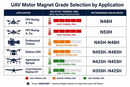
The practical recommendation: for any UAV motor where sustained full-throttle operation is expected - delivery drones, professional cinematography platforms, agricultural sprayers - specify N48H or N50H rather than N52 or N52H. You give up 3–5% in nominal flux density and gain enough coercive force margin to operate safely at 120°C magnet temperature.
3. Grade Selection by UAV Application
| Application | Typical KV Range | Max Magnet Temp | Recommended Grade | Reasoning |
|---|---|---|---|---|
| FPV Racing (3–5 inch) | 2,000–2,800 KV | 100–130°C | N48H | Short bursts, good convection from open frame; H suffix gives thermal margin without sacrificing too much flux |
| FPV Racing (5–7 inch) | 1,200–2,000 KV | 90–120°C | N50H | Larger motor volume improves heat dissipation; N50H hits the flux/coercivity balance well |
| Freestyle / Cinematic (5–7 inch) | 1,700–2,400 KV | 85–115°C | N48H–N50H | Similar to racing but with longer sustained sections; H suffix important |
| Professional Cinema (10–15 inch) | 100–400 KV | 70–100°C | N45H–N48H | Lower electrical frequency reduces core loss; lower KV means lower peak current; N45H often sufficient |
| Delivery / Logistics UAV | 150–600 KV | 100–130°C (nacelle) | N45SH–N48SH | Enclosed nacelle eliminates convective cooling; SH suffix essential for sustained climb at high ambient |
| Agricultural Sprayer | 80–200 KV | 90–120°C | N42SH–N45SH | Long flight durations at partial throttle in high-ambient environments; prioritize Hcj over BHmax |
4. Arc Segment vs Tile Magnet for Outrunner Rotors
Outrunner UAV motors - where the rotor is the outer shell and the stator is fixed - use surface-mounted magnets bonded to the inside of the rotor can. Two geometry choices are available: arc segments curved to match the rotor radius, and flat tiles.
Flat tiles are cheaper to manufacture and easier to source. The problem is that a flat tile on a curved rotor back-iron creates a variable air gap: maximum at the tile edges, minimum at the tile center. In a 22mm stator diameter motor, this variation is small enough to ignore. In a 40mm or larger stator - typical for professional platforms - the air gap variation from flat tiles produces measurable torque ripple at the pole-passing frequency.
For motors above 35mm stator diameter, arc segments matched to the rotor curvature produce a uniform air gap and reduce torque ripple by 40–60% compared to flat tiles of equivalent grade. The cost premium is typically 15–25% over flat tiles at production volumes, which disappears quickly when you account for the vibration isolation savings in the camera gimbal or the reduced structural fatigue in the airframe.
5. Adhesive and Assembly Margin
The thermal expansion coefficient of NdFeB (approximately 5–7 × 10⁻⁶/°C) differs from that of aluminum rotor cans (23 × 10⁻⁶/°C) by roughly 3–4×. Over a 100°C temperature swing, a 15mm arc segment on a 40mm diameter aluminum rotor will see differential expansion of approximately 0.027mm at the bond line.
Standard two-part epoxy adhesives with Shore D hardness above 80 will crack under this cycling if the bond line thickness is less than 0.08mm. The correct approach is a flexible epoxy with Shore D in the 60–75 range and a controlled bond line of 0.10–0.15mm. The magnet supplier should be able to confirm adhesive compatibility with the rotor material and operating temperature range - if they can't, that's information worth having before the first batch of motors goes into field testing.
6. What to Ask Your Magnet Supplier
- ☐ B-H curves at 20°C, 80°C, and 120°C from production material - datasheet typical values are not sufficient
- ☐ Flux density uniformity across a production batch: ±2% is achievable; ±5% is acceptable; above that creates per-motor variation that requires individual calibration
- ☐ Arc segment radius tolerance: ±0.05mm is standard; request ±0.03mm if your nominal air gap is below 0.35mm
- ☐ Adhesive recommendation for your rotor material and operating temperature
- ☐ Salt spray test results if the motor will operate in humid or coastal environments (zinc coating minimum; consider epoxy coating for marine applications)
- ☐ Minimum order quantity for custom arc segments - most suppliers require 500–2,000 pieces for custom geometry; plan your engineering sample quantities accordingly
HIMAGNET supplies arc segment and tile magnets for UAV motors from small-batch engineering samples through production volumes. For grade selection support specific to your motor design, contact our engineering team with your KV, pole count, operating temperature estimate, and rotor geometry.