The Joint Actuator Problem Nobody Talks About
Humanoid robot development has a magnet problem. Not a supply problem - a specification problem.
Most teams building humanoid joints start by pulling a high-grade NdFeB spec from whatever their motor designer used last time. N45SH gets specified because it worked in the last servo project. The thermal suffix gets picked to match the winding temperature limit. And then six months into hardware testing, the joint runs hotter than the model predicted, the torque constant drifts, and nobody can immediately explain why - because the magnet looks fine at room temperature.
The issue is that humanoid robot joint actuators sit at an intersection of constraints that doesn't exist in most other motor applications: extreme torque density, highly intermittent duty cycles, tight thermal envelopes with no forced cooling, and a mechanical package that puts the magnet closer to heat sources than almost any other motor design. Getting the NdFeB selection right requires thinking through all four of those constraints together, not separately.
This article is about how to do that.
1. Why Humanoid Joint Actuators Are Thermally Different
A standard servo motor in an industrial application runs at roughly steady-state thermal equilibrium during production. You size the magnet for continuous duty at rated temperature, add a margin, and the selection is defensible.
Humanoid robot joints don't behave that way. A walking gait cycle involves brief high-torque bursts - peak currents 3–5× the continuous rating - followed by low-load phases where the joint is mostly holding position against gravity. The average current might be modest, but the peak heat generation during those burst phases is concentrated, and the thermal time constant of a compact joint actuator (typically 10–30 seconds for the winding, longer for the magnet assembly) means that the magnet temperature lags the winding temperature by enough to matter.
In a well-characterized test case: a 60mm frameless actuator running a walking gait simulation at 1 Hz showed winding temperatures peaking at 95°C during the stance phase, while the rotor magnet surface temperature reached only 72°C - a lag of roughly 8 seconds. At 2 Hz gait frequency, the lag compresses and the magnet temperature approaches 88°C on the same duty cycle. The magnet grade that's safe at 1 Hz may be running close to its irreversible demagnetization threshold at 2 Hz, with nothing in the steady-state thermal model to flag it.
This is why specifying a humanoid joint magnet from a steady-state thermal model alone is insufficient. The duty cycle dynamics matter.
2. The Demagnetization Risk Is Not Symmetrical
NdFeB demagnetization is not a binary event. There's a gradual irreversible loss of Br that accumulates each time the magnet operates below its knee point on the BH curve - and in a high-pole-count frameless joint motor, the operating point shifts toward the knee under peak current conditions precisely when the joint is doing its highest-torque work.
The practical consequence: a magnet that's thermally safe at 80°C steady-state can still demagnetize partially during a 150ms torque burst if the peak current is high enough to push the operating point below the knee. The amount of demagnetization per cycle is small - maybe 0.1–0.3% Br loss - but it's cumulative. After 10,000 gait cycles, a joint that started at spec can be running 2–4% below its original torque constant. That's enough to cause noticeable asymmetry in bilateral gait, and enough to create closed-loop control headaches that look like software problems.
The fix is straightforward but requires knowing it's necessary: specify the magnet grade based on the peak operating point during maximum current transients, not just the steady-state thermal limit. For most humanoid joint applications, this pushes the selection from standard N-suffix grades toward H or SH - not because the temperature is high, but because the coercive force needs to hold against peak demagnetizing fields.
3. Grade Selection by Joint Position
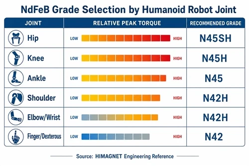
Not all joints in a humanoid robot have the same thermal and electromagnetic environment. A hierarchical approach to grade selection makes sense.
| Joint | Peak Torque | Thermal Environment | Recommended Grade | Rationale |
|---|---|---|---|---|
| Hip (pitch/roll) | High (40–120 N·m) | Enclosed pelvis, limited airflow | N42SH–N45SH | High peak current demagnetization risk; enclosed thermal environment |
| Knee | Highest (60–150 N·m) | Exposed, better convection | N45H–N48H | Peak torque dominant; better cooling allows lower coercivity suffix |
| Ankle | Medium (20–60 N·m) | Exposed, lowest ambient | N45–N48H | Lower thermal risk; standard N acceptable if peak current is controlled |
| Shoulder (pitch/roll) | Medium (15–40 N·m) | Partially enclosed torso | N42H–N45H | Moderate torque density; enclosed but lower duty cycle than legs |
| Elbow / Wrist | Low–Medium (5–20 N·m) | Exposed, good convection | N42–N45H | Lower peak currents; standard N often sufficient with margin |
| Finger / Dexterous | Low (0.1–2 N·m) | Enclosed hand structure | N42H–N45H | Small volume limits heat dissipation; H suffix provides margin |
These are starting points, not final specifications. The actual selection depends on your peak current profile, the thermal resistance of the joint assembly, and whether you have active cooling. But the pattern holds: the joints that carry the most load in the most thermally constrained environments - hips, enclosed shoulder assemblies - need higher Hcj, while the exposed distal joints have more thermal headroom and can run lower coercivity grades.
4. Arc Segment Geometry for High-Pole-Count Joints
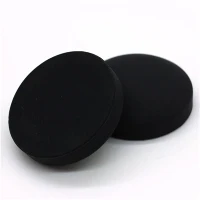
Most humanoid joint actuators use 12–20 pole configurations to maximize torque per ampere in a compact diameter. At this pole count, the arc segment width is narrow - typically 15–25mm chord length for a 60–80mm rotor diameter - and the radial thickness is constrained by the rotor inertia budget.
Two geometry decisions matter more than most teams realize:
Pole arc ratio. A pole arc ratio between 0.82 and 0.90 is the practical range for minimizing cogging torque in high-pole-count frameless motors without sacrificing too much air-gap flux. Going above 0.92 increases flux but cogging becomes the dominant torque ripple source - problematic for a robot joint that needs smooth low-speed position control. Going below 0.80 reduces cogging but cuts torque density enough that you need a higher-grade magnet to compensate, which adds cost without addressing the underlying geometry choice.
Radial thickness vs. back-iron thickness. For N45H-class magnets in a 60–80mm rotor, 3.5–4.5mm radial magnet thickness is the range where the magnets are operating near their optimal working point on the BH curve. Thinner than 3mm and you're leaving flux on the table. Thicker than 5mm adds rotor inertia that shows up as reduced joint bandwidth - a real cost in a robot that needs fast impedance control responses.
5. What Sourcing Separately Costs You
It's common in humanoid robot development programs to source rotor magnets from one supplier and stator laminations from another. The logic makes sense on paper: each supplier optimizes their own component.
In practice, the tolerance stack-up between independently sourced components is the most consistent source of air-gap variation in first-article joint motors. A ±0.05mm variation in magnet arc radius, combined with a ±0.03mm variation in lamination slot radius, produces up to ±0.08mm air-gap variation around the rotor circumference. At a 0.4mm nominal air gap - typical for a high-torque-density frameless joint - that's a 20% variation. The result is measurable torque ripple at the pole-passing frequency, which in a 16-pole motor at 200 RPM (typical slow walking speed) falls at 26 Hz - right in the bandwidth of most humanoid joint impedance controllers.
Matching the magnet arc geometry to the actual lamination geometry from the same production batch eliminates most of that variation. The magnet and lamination don't need to come from the same supplier necessarily, but they do need to be dimensionally co-validated before assembly - and that's far easier when both come from a single source that controls both processes.
6. Practical Checklist for Humanoid Joint Magnet Specification
- ☐ Define peak demagnetizing field at maximum current, not just steady-state operating temperature
- ☐ Run duty-cycle thermal simulation at target gait frequency - 1 Hz and 2 Hz minimum
- ☐ Select grade based on peak operating point with 15% Hcj margin above the knee point at maximum expected magnet temperature
- ☐ Specify arc segment geometry: pole arc ratio 0.82–0.90, radial thickness 3.5–4.5mm for 60–80mm rotor diameter
- ☐ Verify air-gap tolerance budget: magnet arc radius tolerance + lamination slot radius tolerance ≤ 20% of nominal air gap
- ☐ Request B-H curves at 20°C, 80°C, and 120°C from production material - not grade datasheet values
- ☐ For hip and enclosed shoulder joints: specify SH suffix as baseline; H is acceptable only with validated thermal model showing peak magnet temperature ≤ 120°C under worst-case gait
HIMAGNET supplies arc segment magnets matched to customer rotor lamination drawings, with B-H data at multiple temperatures from production material. For humanoid joint programs - from finger actuators to hip torque motors - contact our engineering team with your joint torque, speed, and thermal envelope, and we'll work through the grade selection with you.