Introduction
Electric motors account for the largest single application of NdFeB magnets worldwide. From brushless DC motors in consumer electronics to permanent magnet synchronous motors in electric vehicles, the magnetic circuit design directly determines motor efficiency, torque density, and thermal stability. This guide covers how neodymium magnets are used in electric motors, how to select the right grade for your motor type, and what engineers need to specify when sourcing magnets for motor applications.
Why NdFeB Dominates Motor Applications
1. The Case for Permanent Magnet Motors
Permanent magnet motors replace the electromagnet rotor of conventional induction motors with a rotor carrying high-energy permanent magnets. This eliminates rotor copper losses and reduces the magnetizing current drawn from the inverter, yielding significant efficiency gains - particularly at partial load, where induction motors are least efficient.
The key advantages that make NdFeB the material of choice:
- Highest energy product: 33–52 MGOe, enabling the smallest rotor volume for a given flux requirement
- High remanence: 1.17–1.47 T, producing strong air-gap flux without large magnet cross-sections
- Thin magnet geometry: high coercivity allows thin arc or block magnets, reducing rotor inertia
- No excitation power: unlike wound-field rotors, NdFeB magnets require no continuous electrical input
Motor Types and Magnet Configurations
2. Surface-Mounted Permanent Magnet (SPM) Motors
In SPM motors, arc-segment or tile magnets are bonded or banded to the outer surface of the rotor. This is the simplest configuration and allows the use of standard arc magnets without complex machining.
- Magnet shape: arc segments (curved tiles), typically sintered NdFeB
- Magnetization direction: radial (pointing toward or away from the shaft axis)
- Air gap: larger than IPM motors - the magnet itself occupies part of the magnetic air gap
- Typical grades: N42H to N45SH - moderate energy product with H or SH temperature rating
- Applications: servo motors, spindle motors, small BLDC motors, industrial actuators
Design consideration: arc magnets in SPM rotors are exposed to centrifugal force at high speed. For rotors above 3,000 rpm, retention banding (carbon fiber or stainless steel) is typically required. This reduces the effective magnetic air gap and must be accounted for in flux calculations.
3. Interior Permanent Magnet (IPM) Motors
IPM motors embed rectangular or bar magnets inside the rotor laminations. This protects magnets from centrifugal forces and allows the rotor to exploit reluctance torque in addition to magnet torque, increasing peak torque capability.
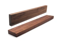
- Magnet shape: rectangular bars or blocks, sometimes trapezoidal
- Magnetization direction: typically parallel (across the short dimension of the bar)
- Air gap: smaller than SPM - only the lamination bridge separates magnet from air gap
- Typical grades: N38SH to N45UH - higher temperature rating critical due to eddy current heating in rotor
- Applications: EV traction motors, HVAC compressors, industrial servo drives, wind turbine generators
Design consideration: IPM rotors experience significant eddy current losses in magnets at high switching frequencies. Segmented magnets (multiple smaller pieces bonded together) reduce eddy current paths and lower magnet operating temperature. Specify segmentation requirements in your drawing if operating at inverter switching frequencies above 5 kHz.
4. Axial Flux Motors
Axial flux motors (also called pancake motors) orient the flux path along the motor shaft axis rather than radially. Disc-shaped magnets are mounted on one or both rotor faces, separated by an air gap from flat stator windings.
- Magnet shape: sector/pie-shaped discs or trapezoidal tiles
- Magnetization direction: axial (parallel to the shaft)
- Typical grades: N42H to N48H - high energy product for compact disc geometry
- Applications: in-wheel EV motors, direct-drive generators, robotics joints, medical imaging
Grade and Temperature Selection for Motors
5. Operating Temperature Is the Critical Variable
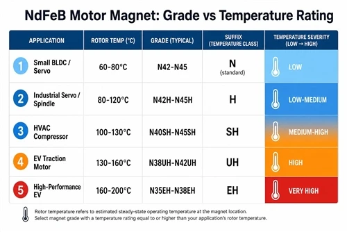
Motor magnets are exposed to heat from both stator winding losses (conducted through the air gap) and their own eddy current losses. Rotor magnet temperature in a loaded motor is typically 20–60°C above ambient - often reaching 100–150°C in EV traction applications.
Specifying the wrong temperature suffix leads to irreversible partial demagnetization under load, which is not recoverable without re-magnetizing the rotor assembly.
| Motor Application | Typical Rotor Temp | Recommended Grade | Min. Temp Suffix |
|---|---|---|---|
| Small BLDC / servo (indoor, light duty) | 60–80°C | N42–N45 | N (standard) |
| Industrial servo / spindle motor | 80–120°C | N42H–N45H | H |
| HVAC compressor / pump motor | 100–130°C | N40SH–N45SH | SH |
| EV traction motor (peak load) | 130–160°C | N38UH–N42UH | UH |
| High-performance EV / motorsport | 160–200°C | N35EH–N38EH | EH |
6. Demagnetization Margin
Motor magnets must maintain adequate demagnetization margin - the distance between the magnet's operating point and its irreversible demagnetization knee on the B-H curve. For motor applications, a minimum margin of 10–15% is standard engineering practice.
The worst-case demagnetization event occurs during a fault condition: a short-circuit current produces a strong opposing field that pushes the operating point down the B-H curve. If this point crosses the knee (particularly at elevated temperature where the knee rises), the magnet will not recover to its original operating point when the fault clears.
Higher coercivity grades (H, SH, UH suffixes) move the knee further down the B-H curve, providing greater demagnetization resistance - at the cost of slightly lower BHmax compared to the same numeric grade without the suffix.
Procurement Checklist for Motor Magnets
7. What Motor Engineers Need to Specify
- Grade with temperature suffix: never specify grade without suffix for motor applications. Minimum H suffix for most industrial motors; SH or UH for EV and high-duty-cycle applications.
- Magnet geometry and tolerance: arc magnets require inner radius (Ri), outer radius (Ro), arc angle, and axial length. Specify radial thickness tolerance (±0.05 mm ground) and arc angle tolerance (±0.1°). For IPM bar magnets, specify all three dimensions with tolerances.
- Magnetization direction and pattern: radial, parallel, or Halbach array. Multi-pole magnetization on a ring is a separate manufacturing step from sintering - confirm your supplier's capability.
- Magnet segmentation: if operating above 5 kHz inverter switching frequency or above 10,000 rpm, specify the number of circumferential and axial segments per pole to limit eddy current losses.
- Coating: motor magnets in enclosed housings typically use Ni-Cu-Ni nickel plating. For oil-cooled motors (direct oil spray cooling), specify epoxy or dual-layer Ni + epoxy coating for chemical resistance.
- B-H curve data at operating temperature: request measured Br and Hcj values at your maximum rotor operating temperature, not only at 20°C. Verify the knee point location at maximum temperature.
- PPAP or first article inspection: for automotive or safety-critical motor applications, require first article inspection (FAI) with full dimensional report and magnetic property certificate per production lot.
How HIMAGNET Supports Motor Applications
HIMAGNET supplies sintered NdFeB arc segments, bar magnets, and disc magnets for motor applications across the full grade and temperature range. We support arc magnet geometries from standard catalog sizes to custom Ri/Ro/arc angle specifications, with ground tolerances to ±0.05 mm.
For motor development programs, we provide B-H curve data at multiple temperatures, demagnetization analysis support, and segmentation recommendations based on your inverter frequency and speed profile.
Share your motor type, rotor geometry, maximum operating temperature, and annual volume - we will recommend the appropriate grade and provide a technical quotation within one business day.