
Linear Motors Use Magnets Differently - And Most Engineers Don't Account For It
Linear motors eliminate the rotary-to-linear mechanical conversion stage - no ballscrew, no rack and pinion, no belt. The force is produced directly in the linear axis. This sounds simpler than a rotary motor driving a screw, and in some ways it is. But the magnet requirements for a linear motor are substantially different from a rotary one, and the differences are not always obvious from the electromagnetics textbook description.
The three most common linear motor configurations are the flat-type (U-channel or ironless forcer), the tubular type, and the voice coil actuator. Each requires different magnet geometry, grade, and specification. This article covers the magnet side of the design decision for each, with specific attention to the applications where specification mistakes are most costly: semiconductor wafer handling, machine tool feed axes, and direct-drive precision stages.
1. U-Channel (Iron-Core and Ironless) Linear Motors: The Magnet Track
The most widely deployed linear motor configuration in machine tools and gantry systems is the U-channel or "linear synchronous motor" format. The stator is a magnet track - a series of NdFeB blocks mounted on a steel backing plate with alternating north-south pole orientation. The forcer (moving part) carries the coil windings and travels along this track, generating thrust force through electromagnetic interaction with the alternating field.
The magnet blocks in a typical U-channel track are 20–50mm wide, 10–30mm long (in the direction of travel), and 5–15mm thick, depending on the motor's force rating. The pole pitch - the center-to-center distance between adjacent magnets of the same polarity - determines the motor's electrical period and directly affects thrust ripple. Shorter pole pitch reduces force ripple but increases the required switching frequency for a given velocity. Most machine tool linear motors use pole pitches of 20–40mm for feed axes running at 1–5 m/s.
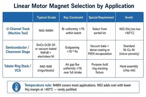
Grade selection for machine tool linear motor tracks is straightforward: N45 or N48 for standard continuous-duty axes, N45SH or N48SH for high-speed spindle-adjacent applications where heat from the stator winding drives track temperature above 80°C. The mistake is specifying N52 to get maximum flux density - at track temperatures above 60°C, the flux density advantage of N52 over N48 narrows significantly (both Br and Hcj degrade with temperature, and N52 has lower Hcj), and the cost premium is not justified. N48H or N48SH covers the same performance envelope at lower cost and with better thermal safety margin.
Magnet-to-magnet consistency within a track assembly is the specification that most affects motion quality. Consecutive magnets with Br variation above ±2% produce a detectable force variation at the pole-pitch spatial frequency - this shows up as a periodic velocity ripple in precision axes. For machine tool feed axes with surface finish requirements below Ra 0.4μm, Br variation within a track batch should be specified at ±1% or better, which requires selecting from a sorted production run rather than random draw.
2. Semiconductor and Electronics Manufacturing: Where Contamination Overrides Grade
Wafer handling systems, photolithography stages, and PCB inspection gantries all use linear motors, but the specification environment is completely different from a machine tool. The dominant constraints are not force density or thermal performance - they are outgassing and particle generation.
Sintered NdFeB magnets in standard nickel coating are not acceptable in Class 10 or Class 100 cleanroom environments. The standard Ni-Cu-Ni coating has micro-porosity that traps and slowly releases hydrocarbon compounds under vacuum, and the coating edges can generate submicron particles if the magnets experience any mechanical contact. Both failure modes are catastrophic for wafer yield.
The correct approach for cleanroom linear motors is one of three options. First, use vacuum-baked NdFeB with electroless nickel or gold overcoat - the vacuum bake drives out most of the trapped outgassing species before the magnet enters the cleanroom, and the denser electroless nickel or gold coating provides a more uniform barrier than electroplated Ni-Cu-Ni. Second, use samarium cobalt (SmCo) magnets, which have lower BHmax than the best NdFeB grades but far lower outgassing rates due to the cobalt-dominant surface chemistry and higher intrinsic chemical stability. For 200mm and 300mm wafer stages running at moderate force requirements, SmCo Gr28 or Gr30 (280–300 kJ/m³ BHmax) is the standard. Third, use fully encapsulated magnet assemblies where each magnet is sealed in a PEEK or ceramic housing - this eliminates direct magnet surface exposure but adds complexity to the track assembly.
The choice between vacuum-baked NdFeB and SmCo is primarily an economic one. NdFeB at equivalent performance rating costs 40–60% less than SmCo. For high-throughput production stages where magnet track cost is significant and the outgassing requirement is satisfied by vacuum bake plus electroless nickel coating, NdFeB is the correct choice. For stages in direct wafer contact or vacuum chambers operating below 10⁻⁵ Pa where any outgassing is unacceptable, SmCo is the correct choice regardless of cost.
3. Tubular Linear Motors: Magnet Ring Stacks and Alternating Polarity
Tubular linear motors - also called linear actuators in some product literature - use a cylindrical arrangement of ring-shaped magnets inside a hollow stator coil assembly. The magnet assembly (the moving "mover" or "shaft") consists of a stack of NdFeB rings with alternating axial magnetization directions separated by soft iron spacers. The rings are typically 20–60mm OD, 8–20mm ID, and 5–15mm thick, depending on force and stroke requirements.
The ring magnet stack works on the same principle as a multi-pole rotary motor, but in the axial direction. North-facing ring, iron spacer, south-facing ring, iron spacer - the flux concentrates in the iron spacers and interacts with the stator coil to produce linear thrust. The key design variable is the ratio of ring height to iron spacer height, which affects the flux density at the air gap and the thrust ripple frequency. Equal ring and spacer heights produce the lowest fundamental ripple; varying the ratio allows ripple harmonic shaping at the cost of reduced average force.
Tubular linear motors are common in direct-drive applications where a long stroke is needed in a compact radial envelope: precision dispensing systems, syringe pump drives, vibration test stands, and pick-and-place machines. For these applications, NdFeB N42 or N45 with standard Ni-Cu-Ni coating is adequate in most cases. The thermal environment is mild (the coil is in the stator, not on the mover, so the magnet shaft runs cool), and the contamination requirements are generally not cleanroom-level.
The assembly challenge with ring stacks is magnetic force during stacking. Axially magnetized rings of the same polarity repel strongly; rings of opposite polarity attract strongly. A stack of 10 rings for a 200mm stroke tubular motor involves forces of 50–200N between adjacent pieces during assembly. Purpose-built assembly fixtures with guide tubes are not optional for this geometry - attempting to assemble ring stacks by hand produces chipped corners and inconsistent spacing in practice, even for experienced assemblers.
4. Voice Coil Actuators: When Force Linearity Matters More Than Peak Force
Voice coil actuators (VCAs) are single-axis, limited-stroke linear actuators where the force is proportional to current across the entire operating stroke. The "voice coil" name comes from loudspeakers - the operating principle is identical. In industrial applications, VCAs are used for fast, precise, short-stroke positioning: autofocus stages, tool force control, vibration isolation, and fast beam steering.
The magnet in a VCA is typically a cylindrical pot magnet assembly with a central pole and an annular outer pole, creating a radial flux gap where the coil moves. What matters is not peak flux density but the uniformity of the radial flux across the full stroke range. A VCA specified for ±10mm stroke must have essentially flat radial flux density throughout the ±10mm range - variation above ±1% causes force non-linearity that must be compensated in the servo controller.
NdFeB grade for VCAs is typically N40–N48, selected to achieve the target air gap flux density with the available magnet volume. The magnet geometry (outer diameter, inner diameter, axial height) is the primary design variable; grade is the fine-tuning parameter. For medical and semiconductor VCA applications, the same outgassing and particle constraints described in Section 2 apply. For industrial automation VCAs without cleanroom requirements, standard sintered NdFeB with Ni-Cu-Ni coating is appropriate and adequate.
HIMAGNET supplies magnet assemblies for U-channel linear motor tracks, tubular motor ring stacks, and voice coil actuators, including vacuum-baked and electroless nickel options for cleanroom applications. Contact our engineering team with your force, stroke, and environment requirements for a geometry recommendation and grade selection analysis.


