
Why Axial Flux Motors Need Different Magnets
Axial flux motors - also called pancake motors or disc motors - orient their magnetic flux parallel to the rotation axis rather than radially outward from it. The air gap is a flat disc rather than a cylindrical annulus. This geometry produces higher torque density per unit volume than radial flux designs, which is why axial flux motors are appearing in EV traction drives, wind generators, direct-drive washing machines, and increasingly in robotics where a short, flat motor fits better than a long cylindrical one.
The magnetic circuit geometry difference is not just a shape change - it changes what magnet geometry is required, how magnetization direction is specified, and what failure modes the magnets are exposed to. Engineers who specify magnets from radial flux motor experience and apply the same logic to axial flux designs typically encounter problems in the first prototype: magnets that are geometrically correct but magnetized in the wrong direction, or designs where the flux concentration factor was not accounted for and the magnets saturate the stator iron at partial load.
1. The Sector Magnet Geometry Problem
In a radial flux motor, the magnets are arc segments - curved tiles that wrap around the cylindrical rotor surface. The magnet width, arc angle, and radial thickness are the key dimensions, and they scale straightforwardly with pole count and rotor diameter.
In an axial flux motor, the magnets are sector-shaped - pie-slice tiles that cover a portion of the flat rotor disc surface. The sector angle equals 360° divided by the number of poles (for a full-coverage design). A 16-pole motor uses 16 sector magnets, each covering 22.5°. The critical geometric complication is that the magnet width varies from the inner radius to the outer radius: the inner edge of each sector is narrower than the outer edge. This is the opposite of a constant cross-section, and it creates two problems.
First, the flux density in the air gap is not uniform across the magnet radius. The outer portion of the magnet produces more flux per unit area than the inner portion at the same magnetization level, because the outer arc is longer and subtends a larger area. In a well-designed axial flux motor, this non-uniformity is managed through stator winding pitch and slot geometry - but the magnet supplier needs to know the inner-to-outer radius ratio and the pole arc fraction to quote the correct geometry.
Second, cutting sector shapes from sintered NdFeB block produces significant material waste compared to arc segments. A block of NdFeB that yields twelve 30° arc segments for a radial motor will yield fewer usable sectors for an axial motor of the same rotor diameter, because the sector corners and the variation in width reduce yield. Expect 20–35% higher material cost per motor for axial flux sector magnets compared to equivalent radial flux arc magnets at the same grade and coating.
2. Magnetization Direction: Axial, Not Radial
This is the single most common specification error for engineers transitioning from radial to axial flux designs. In a radial flux motor, the magnets are magnetized radially - the north and south poles are on the inner and outer curved faces. In an axial flux motor, the magnets are magnetized axially - the north and south poles are on the flat top and bottom faces, oriented parallel to the motor shaft.
Specifying radial magnetization on an axial flux sector magnet produces a magnet that is geometrically correct but magnetically useless in the application - the flux exits through the curved edges rather than through the flat faces where the air gap is. This error is not always caught at incoming inspection because the magnet dimensions are correct; it shows up as near-zero back-EMF when the motor is first run.
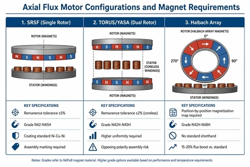
For axial flux motors with Halbach array rotor configurations - increasingly common in high-efficiency designs - the magnetization direction rotates around the rotor disc in 45° or 90° increments. The specification must include the magnetization angle of each magnet position explicitly, and the assembly drawing must mark the orientation of each piece. There is no standard shorthand for this; it requires a position-by-position magnetization map in the purchase specification.
3. Single Rotor vs. Dual Rotor Stator Configurations
Axial flux motors come in three main mechanical configurations: single rotor with single stator (SRSF), dual rotor with single stator (TORUS or YASA-type), and single rotor with dual stator. The magnet specification differs between these configurations.
In TORUS/YASA configurations - where two rotor discs flank a single central coreless stator - each rotor disc carries magnets, and the two discs are assembled with opposing polarity so the flux path closes through the stator winding without a steel core. This means the magnets on each rotor disc must attract toward the opposite disc across the stator gap, and the assembly sequence must maintain this attraction during installation (the force between two opposing rotor discs across a 10mm air gap in a typical 200mm diameter TORUS motor is 500–1500N - enough to seriously injure a hand if the assembly fixture fails).
For coreless TORUS motors, the magnets must be specified with tighter remanence tolerance (±2% vs. the standard ±5%) because there is no iron to saturate and average out small flux non-uniformities. The back-EMF waveform is directly proportional to the local flux density distribution, so magnet-to-magnet variation translates directly into torque ripple. This tighter tolerance requirement typically adds 15–25% to magnet cost.
4. Grade Selection for Axial Flux Applications
The thermal environment in axial flux motors is different from radial flux. The flat disc geometry has better surface-to-volume ratio and in most designs the magnets are closer to the outer perimeter where convective or conductive cooling is more effective. Operating magnet temperatures for axial flux motors in direct-drive traction and generator applications are typically 60–100°C - lower than the 100–150°C seen in high-speed radial flux servo motors.
This means the coercivity requirements are often less severe than expected. For most EV wheel motor and wind generator applications, N42H (120°C rated) is the correct grade. N42SH (150°C) is rarely needed unless the motor is in a high-ambient-temperature environment with limited cooling. Specifying N42SH or higher for a well-cooled axial flux motor adds 8–12% to magnet cost with no performance benefit at operating temperature.
The exception is high-speed axial flux motors - spindle drives, flywheel energy storage rotors - where centrifugal stress on the disc magnets is the dominant design constraint. At 10,000+ RPM, the radial stress on outer-radius sector magnets can approach the tensile strength limit of sintered NdFeB (approximately 80 MPa). These applications require finite element stress analysis of the rotor disc, and in some cases require magnet geometry modifications (adding inner radius chamfers to reduce stress concentration) or switching to bonded NdFeB or SmCo which have better tensile properties at the cost of lower BHmax.
5. Procurement Checklist for Axial Flux Sector Magnets
Standard radial flux magnet purchase specifications need the following additions for axial flux sector magnets:
Geometry: specify inner radius (Ri), outer radius (Ro), sector angle (°), and flat face thickness. Include Ri/Ro ratio explicitly - it determines the yield calculation and the flux distribution uniformity.
Magnetization direction: specify axial (through-thickness) for standard designs. For Halbach array rotors, provide a position-by-position magnetization map drawing.
Remanence tolerance: standard ±5% is acceptable for iron-core stator designs. Specify ±2% for coreless TORUS/YASA configurations.
Coating: standard Ni-Cu-Ni is appropriate for most axial flux applications. For corrosive environments (coastal wind, marine) or high-humidity applications, specify electroless nickel or epoxy overcoat. Gold overcoat is rarely needed unless the motor is in a medical or semiconductor environment.
Assembly marking: request that each magnet face be marked with magnetization direction (N or S) on the flat face. The sector geometry is not self-orienting - unmarked magnets in a multi-pole assembly are a significant assembly error risk.
HIMAGNET produces sector magnets for axial flux motors in grades from N35 to N52, with axial and Halbach-array magnetization, tight-tolerance coreless variants, and assembly marking. Contact our engineering team with your Ri, Ro, pole count, and operating temperature for a geometry and grade recommendation.