Introduction
In small motors - servo actuators, robot joint drives, UAV propulsion units, and dexterous hand motors - efficiency is not a specification you negotiate on paper. It is a consequence of every material choice in the magnetic circuit, including one that engineers sometimes overlook: the thickness of the silicon steel laminations in the stator core.
This guide explains how silicon steel thickness affects iron loss, motor efficiency, and operating temperature in compact high-speed motors, and how to choose between 0.20 mm, 0.27 mm, and 0.35 mm grades for your application.
1. What Is Iron Loss and Why Does It Matter in Small Motors
Iron loss (also called core loss) is the energy dissipated as heat inside the silicon steel core whenever the magnetic field cycles. It has two components:
- Hysteresis loss: energy consumed to realign magnetic domains each cycle. Proportional to frequency and the grade's coercivity.
- Eddy current loss: circulating currents induced in the core by the changing flux. Proportional to the square of both lamination thickness and frequency.
In large low-speed industrial motors running at 50 Hz, eddy current loss is manageable even with 0.50 mm laminations. In small high-speed motors - a servo spinning at 6,000 RPM, a UAV motor at 15,000 RPM, or a frameless dexterous hand motor with 12 pole pairs - the electrical frequency is far higher, and the eddy current penalty for thick laminations becomes severe.
At 6,000 RPM with 6 pole pairs, the electrical frequency is 600 Hz. Eddy current loss scales with the square of thickness: switching from 0.35 mm to 0.20 mm laminations reduces eddy current loss by approximately 67% at the same flux density.
2. The Three Standard Thickness Grades for Small Motor Applications
HIMAGNET works with three lamination thicknesses matched to different motor speed ranges:
| Thickness | Typical Grade | Iron Loss W/kg @ 1T / 400Hz | Best For | Relative Cost |
|---|---|---|---|---|
| 0.35 mm | 35W300 / 35W270 | ~28–35 W/kg | Industrial servo ≤ 3,000 RPM, low-speed torque motors | Low |
| 0.27 mm | 27W230 / 27W250 | ~18–24 W/kg | Mid-speed servo 3,000–8,000 RPM, robot joint actuators | Medium |
| 0.20 mm | 20W1200H / 20W1500H | ~10–14 W/kg | High-speed motors ≥ 8,000 RPM, UAV, dexterous hand frameless motors | High |
The W/kg figures are indicative at 400 Hz / 1 T. Actual losses depend on flux density, frequency, and grade - always verify with the lamination datasheet for your operating point.
3. How Iron Loss Affects Motor Efficiency and Thermal Headroom
Iron loss directly adds to motor heat generation. In a compact motor with limited thermal mass and surface area, excess iron loss raises winding temperature, accelerates insulation aging, and may trigger thermal derating before rated torque is reached.
Consider a 60 W servo motor core with 0.35 mm laminations generating 8 W of iron loss at its operating speed. Switching to 0.20 mm laminations reduces that to approximately 2.5 W - a saving of 5.5 W. In a motor this size, that difference:
- Reduces steady-state winding temperature by an estimated 15–25°C (depending on thermal resistance)
- Allows approximately 8–12% higher continuous torque before thermal limit
- Extends motor service life by reducing thermal cycling stress on windings and magnets
For NdFeB magnets, lower operating temperature also means a better safety margin against irreversible demagnetization - a critical consideration when specifying grades like N42H or N45SH that have moderate coercivity.
4. Interaction Between Lamination Thickness and Magnet Grade
Silicon steel selection and magnet grade selection are not independent decisions. They interact through the working point on the magnet's BH curve and through heat management:
- Thicker laminations → higher iron loss → higher operating temperature → magnets need higher Hcj (coercive force) to avoid demagnetization. This typically means specifying an H or SH suffix grade instead of standard N.
- Thinner laminations → lower iron loss → lower temperature → standard N or M suffix magnet grades may be sufficient, reducing magnet cost.
This is why HIMAGNET evaluates lamination and magnet selection together as part of the motor design review - optimizing both independently often results in over-specified magnets compensating for avoidable iron loss.
5. Stamping Precision and Slot Geometry at Thin Gauges
Thinner laminations are not only a materials question - they demand tighter stamping precision. At 0.20 mm, burr height must be controlled to below 0.015 mm to ensure tight stacking and avoid inter-lamination shorts that would negate the efficiency gain.
Key manufacturing requirements for thin laminations:
- Progressive die stamping with fine-pitch tooling to maintain slot geometry tolerances
- Burr-free edges: controlled by die clearance (typically 3–5% of material thickness) and tool maintenance schedule
- Stacking factor ≥ 0.97: verified by measuring the compressed stack height against the theoretical solid height
- Insulation coating: C-5 or C-6 grade inorganic coating for motors operating above 150°C
HIMAGNET's in-house stamping capability covers lamination thicknesses from 0.20 mm to 0.50 mm with slot geometries down to 0.8 mm bridge width - matching the requirements of high pole-count small motors used in robotics and UAV applications.
6. Selection Guide: Matching Lamination Thickness to Your Motor
| Application | Speed Range | Pole Pairs | Electrical Frequency | Recommended Thickness |
|---|---|---|---|---|
| Industrial servo motor | ≤ 3,000 RPM | 3–4 | ≤ 200 Hz | 0.35 mm |
| Robot joint actuator | 3,000–6,000 RPM | 5–7 | 250–700 Hz | 0.27 mm |
| Dexterous hand frameless motor | 2,000–5,000 RPM | 8–12 | 270–1,000 Hz | 0.20 mm |
| UAV propulsion motor | 8,000–20,000 RPM | 7–14 | 930–4,700 Hz | 0.20 mm |
| High-speed spindle | 15,000–60,000 RPM | 2–3 | 500–3,000 Hz | 0.20 mm or thinner |
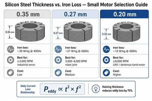
When electrical frequency exceeds 400 Hz, 0.20 mm laminations become the practical baseline. Below 200 Hz, 0.35 mm is cost-effective and mechanically easier to stack.
7. Procurement Checklist for Silicon Steel Laminations
When sourcing laminations for small motor development, verify the following with your supplier:
- ☐ Confirm iron loss W/kg at your actual operating frequency and flux density (not just the standard 50 Hz / 1.5 T datasheet value)
- ☐ Request stacking factor measurement report (target ≥ 0.97 for 0.20–0.27 mm)
- ☐ Specify insulation coating grade (C-5 for standard motors, C-6 for high-temperature)
- ☐ Confirm burr height tolerance (≤ 0.015 mm for 0.20 mm material)
- ☐ Request a sample stack for dimensional inspection before committing to production tooling
- ☐ Align lamination selection with your magnet grade review - thin laminations may allow a step down in magnet Hcj suffix
HIMAGNET supplies matched lamination and magnet packages for small motor development, with engineering support for grade selection, thermal modeling, and prototype validation. Contact our team to discuss your motor specification.