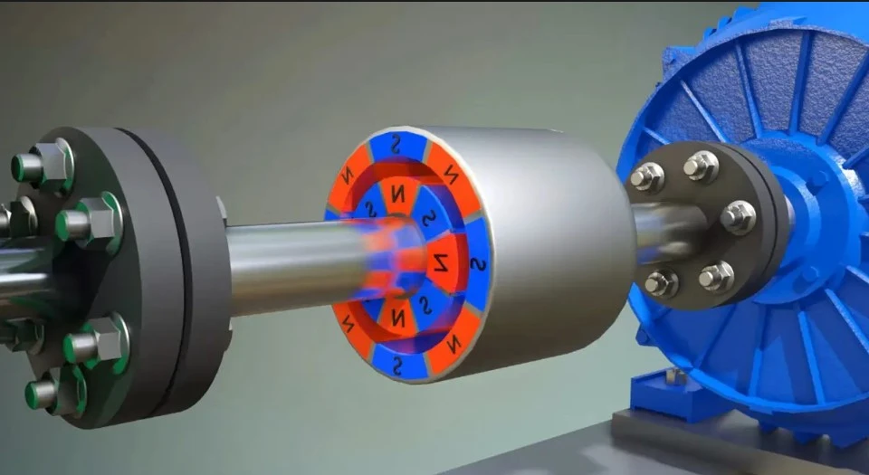
eliminating dynamic seals that wear and leak. For hermetically sealed pumps handling corrosive or hazardous fluids (e.g., chemical processing, pharmaceutical, nuclear), magnetic drives are mandatory to achieve zero emissions. The coupling consists of an inner rotor (attached to the pump impeller) and an outer rotor (driven by the motor), with magnets arranged in alternating poles. This guide explains how sealless magnetic drives eliminate fluid leaks, covers inner vs. outer rotor pole matching and torque transmission, explains why SmCo is preferred for high-temperature chemical pumps, and details balancing air gaps and containment shell thickness.
Eliminating Fluid Leaks: The Mechanics of Sealless Magnetic Drives
Conventional centrifugal pumps use a mechanical seal (carbon/ceramic faces) that rides on the pump shaft. Wear and thermal shock cause seal failure, resulting in fluid leakage-unsafe for toxic, flammable, or high-purity fluids. In a magnetic drive pump:
The motor rotates an outer magnet assembly (outer rotor) outside a sealed containment shell.
The inner magnet assembly (inner rotor, on the pump shaft) is magnetically locked to the outer rotor.
Torque transmits through the containment shell wall (typically 1-3mm thick Hastelloy or titanium) without any shaft penetration.
The only seals are static O-rings on the shell, which are reliable and maintenance-free.
No dynamic seals = zero leakage. Magnetic couplings are standard for pumps handling:
Highly corrosive acids (HCl, H2SO4, HF)
Flammable solvents (acetone, methanol, toluene)
High-purity water (pharma, semiconductor)
High-temperature thermal oils (>200°C)
Inner vs. Outer Rotors: Pole Matching and Torque Transmission
The inner and outer rotors must have identical pole counts and pole arc alignment. Standard configurations:
4-pole, 6-pole, or 8-pole designs. Higher pole count reduces rotor diameter and inertia but requires tighter air gap.
Magnetic materials: Sintered NdFeB (N42SH) for temperatures up to 100°C, SmCo for >100°C. For chemical pumps, SmCo is standard because of corrosion resistance (no coating required) and thermal stability.
Magnet arrangement: Surface-mounted magnets on both rotors (SPM) for simple assembly; or interior magnets (IPM) with flux concentration for higher torque density.
Torque transmission equation: T = k × Br² × (OD³ - ID³) × sin(δ) / (gap² + shell thickness²), where δ is the angular displacement (pull-out angle). The maximum torque (pull-out torque) occurs at δ = 90° (magnetic poles misaligned by 90°). Operating torque should be <80% of pull-out torque to avoid decoupling.
If the motor overloads or jams, the magnetic coupling slips (decouples) harmlessly, acting as a torque limiter. This protects the motor and pump from mechanical damage.
Why Samarium Cobalt (SmCo) is Preferred for High-Temp Chemical Pumps
Chemical pumps often handle fluids at 150-300°C. NdFeB loses significant Br and Hcj above 100°C, and its susceptibility to corrosion requires expensive coating (which may peel under thermal cycling). SmCo (2:17 grade) offers:
Br = 10.5-11.5 kGs (lower than NdFeB but stable up to 300°C).
Hcj > 20 kOe at 20°C, remaining >10 kOe at 250°C.
Corrosion resistance: SmCo does not require coating for most chemical fluids (except hydrofluoric acid).
Coefficient of thermal expansion matches Hastelloy containment shells, reducing stress.
For cryogenic applications (-40°C to -150°C), NdFeB is acceptable because low temperatures do not demagnetize. However, SmCo also performs well at low temperatures.
Selection guideline: If fluid temperature >120°C, specify SmCo. If fluid temperature <120°C and the pump is dry-mount (no fluid splashing on the magnets), NdFeB with Ni-Cu-Ni coating is sufficient.
Balancing Air Gaps and Containment Shell Thickness
The air gap between inner and outer rotors includes:
The containment shell wall thickness (critical for pressure rating).
The running clearance between magnets and shell (typically 0.5-2mm per side).
Total air gap = shell thickness + 2 × clearance.
A larger air gap reduces torque transmission (roughly inverse square law). For a fixed torque requirement, increasing the air gap by 1mm requires increasing magnet OD by 20% to compensate, adding cost and inertia. Therefore, design optimization must balance:
| Fluid Pressure | Containment Shell Material | Shell Thickness (mm) | Air Gap (mm) | Torque Reduction (vs 3mm gap) |
|---|---|---|---|---|
| <10 bar | Stainless 316L | 1.0-1.5 | 2.5-3.5 | Baseline |
| 10-30 bar | Hastelloy C276 | 1.5-2.5 | 3.5-4.5 | -25% to -35% |
| >30 bar | Titanium (Ti-6Al-4V) | 2.0-3.0 | 4.0-5.0 | -40% to -50% |
| High temp (>200°C) | Inconel 625 | 2.0-3.0 | 4.0-5.0 | -40% to -50% |
For high-torque, high-pressure applications, we use radial magnet orientation or Halbach arrays to compensate for the increased air gap. FEA simulation is essential to predict pull-out torque and temperature rise from eddy currents in the containment shell.
For magnetic couplings and sealed pump assemblies, including complete inner/outer rotor sets with SmCo or NdFeB magnets, please visit our Magnetic Motor Assemblies and Samarium Cobalt Magnets pages on our website.
To request a coupling design for your pump specifications-including torque, speed, fluid temperature, and pressure-contact our magnetic coupling engineering team.
Frequently Asked Questions
Q: What happens if the magnetic coupling decouples (pulls out) during operation?
A: The inner rotor stops rotating (pump stalls), and the outer rotor spins freely. The motor draws lower current (no load). To re-couple, shut down the motor, wait for the fluid pressure to drop, then restart. The magnets automatically re-lock when both rotors are stationary. Repeated decoupling does not damage the magnets.
Q: Can we use a magnetic coupling for a pump handling abrasive slurries?
A: Yes, but the containment shell wear from abrasives is a concern. Use a double-containment shell with a flush fluid (clean liquid) circulated between the inner and outer shells to protect the magnets and prevent slurry intrusion. We supply this configuration.
Q: How do you measure the air gap in an assembled magnetic coupling?
A: Use a feeler gauge or ultrasonic thickness measurement through the shell. For factory assembly, we use a precision alignment jig to set the gap within ±0.1mm. We provide an air gap measurement report with each coupling.