How Coating Thickness Affects Magnet Tolerance and Assembly Fit
Introduction
One of the most common quality issues in custom magnet projects happens after production is complete: the magnet dimensions are correct, but it does not fit the assembly.
The culprit is often coating thickness. When a magnet is coated, every surface gains thickness. This can add up to 0.05 mm, 0.10 mm or even 0.20 mm to the overall dimension-depending on the coating type and process.
For industrial buyers, this is not just a technical detail. It directly affects whether the magnet will fit into a motor slot, press into a sensor housing, or slide smoothly into a mechanical fixture.
Why Coating Adds Dimension
Sintered NdFeB magnets are highly susceptible to corrosion. To protect them, the finished magnet is coated with nickel, zinc, epoxy, or other protective layers.
This coating is applied to all exposed magnet surfaces:
- Top and bottom (for a disc)
- All four sides (for a block)
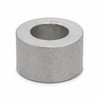
- Inner and outer diameter (for a ring)
- Edges and corners (everywhere exposed)
Each surface gets coated, which means the dimension grows. For example, if a nickel coating is 10 microns thick on all sides of a disc, the diameter increases by 20 microns (10 microns on each side).

Coating Thickness Varies by Type
Different coatings have different typical thicknesses:
| Coating Type | Typical Single-Side Thickness | Total Diameter Increase (Disc) | Common Use |
|---|---|---|---|
| Nickel | 10-20 microns | 20-40 microns (0.02-0.04 mm) | General industrial |
| Zinc | 5-15 microns | 10-30 microns (0.01-0.03 mm) | Cost-sensitive projects |
| Epoxy | 15-25 microns | 30-50 microns (0.03-0.05 mm) | Humid environments |
| Nickel + Epoxy | 20-35 microns | 40-70 microns (0.04-0.07 mm) | Marine/outdoor |
| PTFE | 10-30 microns | 20-60 microns (0.02-0.06 mm) | High-temperature |
Notice that coating thickness is not always consistent. Suppliers typically specify "10-20 microns" because the actual thickness depends on the process conditions, magnet surface area, and bath concentration. Thickness can also vary across different surfaces of the same magnet.
The Tolerance Problem: Before Coating vs. After Coating
This is where the confusion starts. When a buyer specifies a magnet dimension of, say, 10 mm diameter, the question is:
Is this the dimension before coating or after coating?
- Before coating (machined size): The sintered NdFeB is measured without any protective layer. This is the base dimension before coating is applied.
- After coating (final assembly size): The magnet is measured after the coating process is complete. This is the size that goes into the final product assembly.
Many first-time buyers assume the specification is the final size (after coating), but suppliers sometimes interpret it as the base size. This mismatch causes the magnet to be too large or too small after coating.
For example:
- Buyer's requirement: 10.00 mm ± 0.05 mm diameter (assumes final size after coating)
- Supplier's production: 10.00 mm ± 0.05 mm before coating, then nickel coating added (adds ~0.03 mm)
- Result: 10.03 mm magnet, which is 0.03 mm too large for the 10.00 mm assembly hole
- Outcome: The magnet does not fit; assembly delays or rework required
Common Assembly Fit Problems Caused by Coating
1. Motor slots too tight
- Motor rotor magnets must slide into slots with tight mechanical fit
- Coating adds unexpected dimension
- Magnets jam or break during insertion
- Solution: Confirm whether the slot drawing dimension is before or after coating
2. Sensor housing does not close
- Magnet pressed into a plastic or metal housing
- Coating thickness causes interference with the housing wall
- Housing cracks or magnet protrudes
- Solution: Account for coating thickness in the housing bore dimension
3. Press-fit assemblies fail
- Coupling or bearing magnets pressed onto a shaft
- Coating adds diameter, changing the interference fit
- Press force becomes too high; shaft or magnet damage
- Solution: Verify coating thickness against press-fit tolerance stack
4. Magnetic assembly gaps
- Multiple magnets assembled into a magnetic array
- Coating thickness affects spacing
- Gaps change the magnetic field pattern
- Performance drops
- Solution: Include coating thickness in spacing calculations
How to Specify Tolerance Correctly When Coating Is Involved
To avoid coating-thickness problems, use clear language in your drawing or specification:
Method 1: Specify "After Coating" Dimension (Recommended for Final Assembly)
"Magnet dimension: 10.00 mm ± 0.05 mm diameter after coating"
This is the final size that must fit into the assembly. The supplier controls the base dimension and coating thickness to achieve this final tolerance.
Method 2: Specify "Before Coating" + Coating Thickness
"Magnet dimension: 9.95 mm ± 0.05 mm diameter before coating. Coating: nickel, 15 ± 5 microns per side. Final dimension after coating: 10.03 ± 0.07 mm (approximately)."
This gives the supplier explicit control and allows you to calculate the final size.
Method 3: Specify Tolerance on the Coated Dimension and Coating Range
"Magnet dimension: 10.00 mm ± 0.05 mm final assembly size (after coating). Coating thickness: 10-20 microns. Tolerance stack acceptable if final size stays within 10.00 ± 0.05 mm."
Tolerance Stack: The Hidden Dimension Multiplier
When you coat a magnet, tolerance can stack up. Here's why:
For a disc magnet with diameter D and coating thickness T on each side:
- Final diameter = (Base diameter) + 2T
- Tolerance variation compounds
Example calculation:
- Base tolerance: ± 0.05 mm
- Coating tolerance: ± 5 microns per side (±0.005 mm per side)
- Total tolerance after coating: ± 0.05 + ±0.01 = ± 0.06 mm (approximately)
This means the final assembled magnet might be anywhere from 9.94 mm to 10.06 mm instead of the expected 10.00 ± 0.05 mm.
If the assembly housing bore is 10.00 ± 0.02 mm, the magnet will not fit reliably. This is why tight-fit and precision assemblies need special attention to coating thickness.
Epoxy Coating: Extra Caution for Tight Fits
Epoxy coating is thicker than nickel, typically 15-25 microns per side. This means epoxy-coated magnets can be 30-50 microns (0.03-0.05 mm) larger in diameter than the base magnet.
If you need epoxy coating for corrosion protection but also have tight mechanical tolerances, inform the supplier early. They may recommend:
- Tighter base tolerance to compensate
- Thinner epoxy (if possible)
- Selective coating (coat only exposed surfaces, not assembly-fit surfaces)
- Or choose a different coating like nickel, which is thinner
How HIMAGNET Handles Coating and Tolerance
HIMAGNET works with buyers to clarify tolerance specifications before production. Our process includes:
- Confirmation call: We confirm whether the dimension is before coating, after coating, or both
- Coating selection: We recommend coating type and thickness based on the environment and tolerance requirement
- Tolerance stack analysis: We calculate the expected final dimension including coating tolerance
- SPC process: During production, we use statistical process control (SPC) to monitor coating thickness and final dimension
- Dimensional report: We provide a dimensional report or SPC chart to confirm the coated magnet meets the spec
For critical assemblies, we can also provide Gaussmeter traces or dimensional verification beyond standard tolerance.
Have you experienced magnet fit problems in your assembly? Or are you specifying a custom magnet with tight tolerances and surface coating?
Share your assembly drawing, required final tolerance, coating preference and application details with HIMAGNET. Our team will verify the coating thickness impact and ensure your magnet fits correctly on the first try.