Pole-Slot Combinations in BLDC Motors: Why the Numbers Matter More Than Most Engineers Think
The choice of pole count and slot count in a BLDC motor is not a single design variable - it's a pair that determines cogging torque, winding factor, harmonic content, and manufacturing complexity simultaneously. Most motor textbooks explain the relationship in general terms. This article gives the engineering specifics: the numbers to use, the numbers to avoid, and the trade-offs that don't appear in simplified comparisons.
The discussion assumes permanent magnet brushless DC motors (surface-mount or interior) with sintered NdFeB magnets, operating in servo, direct-drive, or high-efficiency industrial applications. Consumer motors with relaxed cogging and efficiency requirements follow different trade-off logic.
1. The LCM Rule for Cogging Torque
Cogging torque - the reluctance torque variation as the rotor moves relative to the stator slots - has a spatial period determined by the least common multiple (LCM) of pole count and slot count. Specifically, the number of cogging torque cycles per mechanical revolution equals LCM(2p, Q), where 2p is the number of poles and Q is the number of slots.
Higher LCM means more cogging cycles per revolution, which means lower peak cogging torque magnitude for the same magnetic circuit geometry. A 6-slot/4-pole motor has LCM(4,6) = 12 - 12 cogging pulses per revolution, each relatively large. A 12-slot/10-pole motor has LCM(10,12) = 60 - 60 pulses per revolution at lower individual amplitude. A 24-slot/22-pole motor has LCM(22,24) = 264. This is why high pole-count fractional-slot concentrated winding (FSCW) motors have become the standard for direct-drive servo applications.
The trade-off: high pole count at a given speed means high electrical frequency, which increases core losses. At 3,000 rpm with 10 poles (5 pole pairs), electrical frequency = 3000 × 5 / 60 = 250 Hz. With 22 poles, it's 550 Hz. Silicon steel hysteresis and eddy-current losses scale with frequency - thinner laminations (0.20 mm or less) become necessary to keep core losses manageable above 400 Hz. Budget an additional 15–25% for lamination material cost when moving from 0.35 mm to 0.20 mm steel in a high-pole-count design.
2. Winding Factor: Integer-Slot vs Fractional-Slot
The winding factor (kw) quantifies how effectively the winding arrangement converts current into torque. It combines the distribution factor and the pitch factor. For integer-slot distributed windings (the traditional arrangement where slots per pole per phase = integer), kw typically falls in the range 0.93–0.96 for the fundamental. For fractional-slot concentrated windings (FSCW) where slots per pole per phase is a fraction, kw is lower - typically 0.86–0.93 - but the arrangement eliminates end-winding overhang and allows very high pole counts in short axial length motors.
The practical meaning: a motor with kw = 0.866 produces about 9% less torque than one with kw = 0.933 at the same current and magnet flux, all else equal. For a 10 kW motor, that's a meaningful difference. FSCW motors compensate with shorter end windings (lower copper loss, lower total weight) and higher pole counts (lower cogging), but the fundamental torque constant is lower. Specify kw explicitly in your motor requirements if torque density is critical.
For the 12-slot/10-pole combination specifically: the winding factor is 0.933 for the fundamental with single-layer winding. This combination is widely used because it achieves a high LCM (60), acceptable kw, and short end windings. It's a reasonable first choice for compact, low-cogging servo motors in the 100W–5kW range.
3. Common Combinations and Their Engineering Trade-offs
Rather than listing all possible combinations, the following covers the configurations that appear most often in precision servo and direct-drive motor designs, with the engineering basis for each.
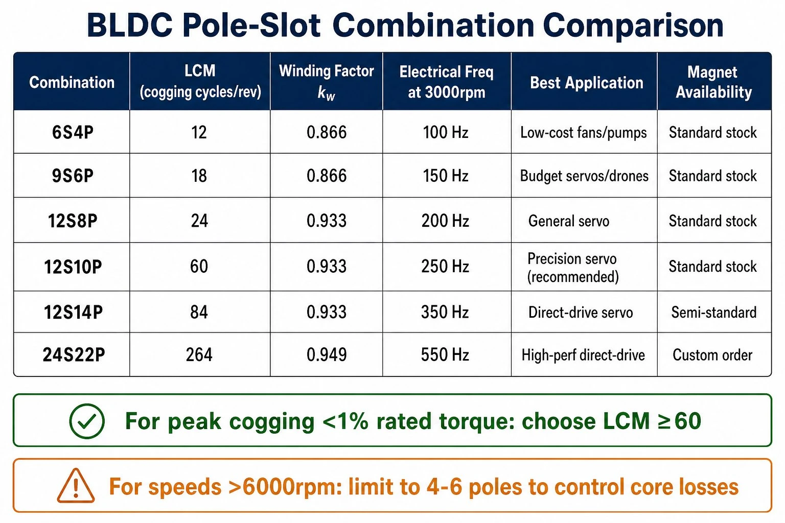
6 slots / 4 poles (6S4P): LCM = 12, kw = 0.866. High cogging relative to motor size. Simple winding. Appropriate for low-cost applications where cogging is not specified, or where mechanical stiffness and closed-loop control compensate. Not appropriate for direct-drive applications or any servo with a cogging torque requirement below 3% of rated torque.
9 slots / 6 poles (9S6P): LCM = 18, kw = 0.866. Slightly better cogging than 6S4P for the same physical size. Common in low-cost drone motors and fans. The 3-phase winding is straightforward. Winding factor is the same as 6S4P - this combination's main advantage is physical compactness rather than electromagnetic performance.
12 slots / 8 poles (12S8P): LCM = 24, kw = 0.933. Better cogging than 9S6P. This is a reasonable general-purpose servo combination for applications with moderate cogging specifications (peak cogging below 2% of rated torque achievable with magnet shaping). The winding factor improvement over 9S6P is real - expect about 7% higher torque constant for the same copper fill.
12 slots / 10 poles (12S10P): LCM = 60, kw = 0.933. The most commonly specified combination for precision servo motors in the 100W–2kW range. Very low cogging relative to motor size - LCM = 60 means 60 cogging cycles per revolution, each with low amplitude. Single-layer winding is standard. The 10-pole configuration at typical servo speeds (3,000 rpm continuous) runs at 250 Hz electrical frequency - compatible with 0.35 mm silicon steel. For higher speeds (>6,000 rpm), move to 0.27 mm or 0.20 mm laminations.
12 slots / 14 poles (12S14P): LCM = 84, kw = 0.933. Lower cogging than 12S10P with the same kw. Used in direct-drive applications where peak cogging below 1% of rated torque is specified. The higher pole count means higher electrical frequency at a given mechanical speed - less suitable for high-speed operation, well-suited for direct-drive wheel motors, rotary tables, and low-speed servo axes.
18 slots / 12 poles (18S12P): LCM = 36, kw = 0.866 (single-layer), 0.933 (double-layer with short pitch). This combination allows distributed winding with 3 slots per pole per phase, giving higher harmonic quality than concentrated windings. Preferred in applications requiring smooth torque at all speeds, including low-speed positioning. Core losses are moderate due to the 12-pole configuration.
24 slots / 22 poles (24S22P): LCM = 264, kw = 0.949. Very low cogging, high torque density per unit axial length. Used in high-performance direct-drive applications - robotic joint actuators, precision rotary stages. The winding factor is higher than most FSCW combinations. The main limitation is manufacturing complexity: 22-pole rotor magnets require tight positional tolerance during assembly, and the high pole count raises electrical frequency to 550+ Hz at 3,000 rpm mechanical, requiring 0.20 mm laminations and precise stacking.
4. Magnet Arc Coverage and Its Effect on Cogging
The pole-slot combination determines the spatial frequency of cogging, but magnet arc coverage (the ratio of magnet angular width to pole pitch) determines the amplitude of the dominant cogging harmonic. Fractional arc coverage - typically 0.80–0.87 of pole pitch - introduces a flux variation that can partially cancel the slot-driven cogging harmonics if tuned correctly.
For a 12S10P motor, the dominant cogging harmonic after LCM correction is the 60th mechanical harmonic. Magnet arc optimization shifts the amplitude of this harmonic. In practice, arc coverage of 0.833 (5/6 of pole pitch) gives near-zero cogging for ideal sinusoidal magnet magnetization in a 12S10P configuration. Real sintered NdFeB arc magnets deviate from ideal sinusoidal flux density, so expect residual cogging of 0.3–0.8% of rated torque with standard arc magnets and 0.1–0.3% with flux-focused arc magnets or skewed magnets.
Magnet skewing (rotating the magnet pattern axially along the motor stack) can further reduce cogging at the cost of manufacturing complexity and a small reduction in average torque (typically 2–5% torque loss for one-slot skew). For most servo applications, magnet arc optimization alone achieves the cogging specification without skewing. Add skew only when the cogging specification is below 0.3% of rated torque and magnet arc optimization alone is insufficient.
5. Selection Criteria Summary
The selection process in practice:
First, define the cogging torque requirement. If the application requires peak cogging below 1% of rated torque (direct-drive servo, precision positioning), choose a pole-slot combination with LCM ≥ 60. If the requirement is 1–3% (standard servo, high-performance motion), LCM ≥ 24 is usually sufficient. If cogging is not specified (fan, pump, low-cost motor), use the simplest combination (6S4P, 9S6P) for manufacturing cost savings.
Second, define the speed range. High-speed (>6,000 rpm) applications require lower pole counts to keep electrical frequency manageable. A 12S10P motor at 10,000 rpm runs at 833 Hz - core losses become problematic without ultra-thin laminations (0.15–0.20 mm). For high-speed applications, 4-pole or 6-pole configurations with correspondingly fewer slots are more practical even if cogging performance is worse.
Third, consider axial length constraints. FSCW motors (12S10P, 12S14P, 24S22P) have very short end windings and are efficient in short-axial formats. For pancake (disc-type) motors or wheel motors with severe axial constraints, these combinations are preferred. For longer-aspect-ratio motors where end winding volume is not a significant constraint, distributed winding (18S12P, 24S18P) gives better harmonic quality and smoother torque at low speed.
Fourth, check the magnet supply. Unusual pole counts (e.g., 22 poles) require arc magnets with precise sector angles that are not standard catalog items - lead time is 4–6 weeks for custom arc magnets, compared to 2–3 weeks for 4-, 6-, 8-, or 10-pole standard arc segment stock. If development schedule requires rapid prototyping, favor pole counts for which standard arc magnets are available (4, 6, 8, 10 poles are all standard; 12 and 14 poles are semi-standard; 18+ poles require custom orders).
A direct-drive servo operating at 300 rpm with a cogging specification of 0.5% rated torque and a 150 mm stator outer diameter would point clearly to 24S22P: LCM = 264, kw = 0.949, and the low speed means electrical frequency is only 55 Hz at 300 rpm (12 pole pairs × 5 rev/sec) - completely manageable with 0.35 mm silicon steel. The magnet supply for 22-pole arc segments requires custom ordering, which adds 3–4 weeks to the first prototype cycle. Plan accordingly.
Contact HIMAGNET
HIMAGNET supplies NdFeB arc segment magnets for all standard and custom pole counts. For 10-pole, 14-pole, and custom configurations, contact our engineering team with your stator OD, rotor ID, and pole arc angle for a quotation. Email: info@himagnet.com